



In renovation, remodeling, or office repurposing projects, accurately capturing the current state is the foundation for proposing appropriate design solutions. With Scan2BIM combined with VinaCAD Web Engine, the actual space is digitized into a 3D Model, which is then used to verify the current state, design layouts, and create CAD/DXF drawings.
In this case study, an office area of approximately 200 m² digitized using LiDAR-integrated devices combined with Scan2BIM. The 3D model is then imported into VinaCAD Web Engine for inspection, layout design, and the use of AI to support the creation of additional layout options.
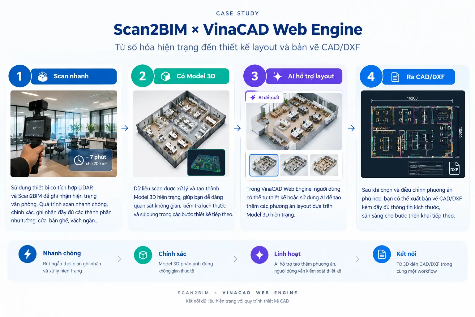
Figure 1. Workflow from as-built digitization to layout design and CAD/DXF drawings.
1. As-built digitization with Scan2BIM
The first step is to directly record the actual space using a LiDAR-integrated device combined with Scan2BIM. In this case study, an office area of approximately 200 m² was scanned to record existing components such as walls, doors, tables, chairs, partitions, and the spatial arrangement.
The scanning process aims to convert the physical space into an as-built 3D Model, creating input data for subsequent processing steps.
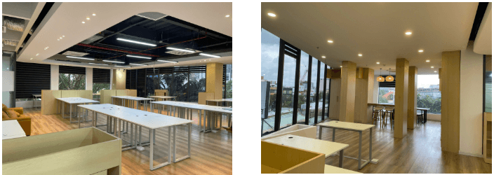
Figure 2. Current state of the office, approximately 200 m², before digitization.
From scan data to 3D Model
While moving through the space, data is recorded and the 3D Model is gradually formed. The operator can track the scanned areas and continue recording the remaining parts of the space.
In this case study, the entire area of approximately 200 m² was scanned in about 7 minutes.
Video 1. The process of scanning the current state using LiDAR-integrated equipment and Scan2BIM.
After the scanning process, the data is converted into a 3D Model of the current state.
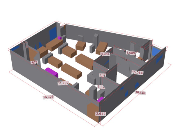
Automatic 3D Model DIM after Scan
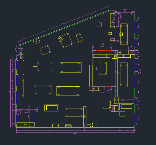
DXF file - automatic DIM after scan
Figure 3. 3D and 2D Models created from as-built scan data.
From here, the physical space has been converted into 3D data that can be further used in the design environment.
2. Import 3D Model into VinaCAD Web Engine
After obtaining the 3D Model, the workflow shifts from as-built digitization to design verification and development. The 3D Model is imported into VinaCAD Web Engine, creating a working environment continuing from scan data.
Video 2 – The current 3D Model is imported into VinaCAD Web Engine
Instead of starting over from a blank floor plan, users can continue working on data from the actual space.
In VinaCAD Web Engine, the 3D Model can be used to:
- Check space dimensions
- Observe and confirm the current layout
- Develop new layout options
- Serve as a basis for creating CAD/DXF drawings.
Check current status before designing
Before changing the layout, users can check information such as area dimensions, distances between objects, positions of tables and chairs, and available spaces for the new arrangement.
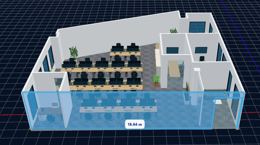
Figure 4.Check dimensions and space on the 3D Model.
The current layout is also visually reviewed on the 3D model to determine which components to keep, change, and which spaces can be rearranged.
After this step, the current 3D Model becomes the basis for developing the design plan.
3. Layout design with AI support
After clearly understanding the current status, the next step is to develop a new arrangement plan.
With VinaCAD Web Engine, users can proactively design layouts as required or use AI integrated directly into the system to support creating additional layout options.
Custom design on demand
Once a specific idea is established, users can proactively build and adjust the layout based on the current 3D Model.
Video 3- Custom layout design with AI support
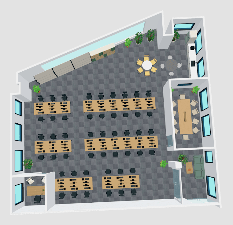
Figure 5. The layout option is constructed and adjusted on the VinaCAD Web Engine.
This approach is suitable when the designer has predetermined the spatial organization or specific project requirements.
AI supports creating additional options
In cases where one wants to explore further layout possibilities, the AI integrated directly into the VinaCAD Web Engine can support creating layout options based on current spatial data.
Notably, the AI does not operate on a completely empty floor plan. The option is created based on 3D Model digitized from actual space.
Video 4. AI supports creating layout options based on the current 3D Model.
The generated options can be reviewed, selected, and further adjusted according to actual requirements.
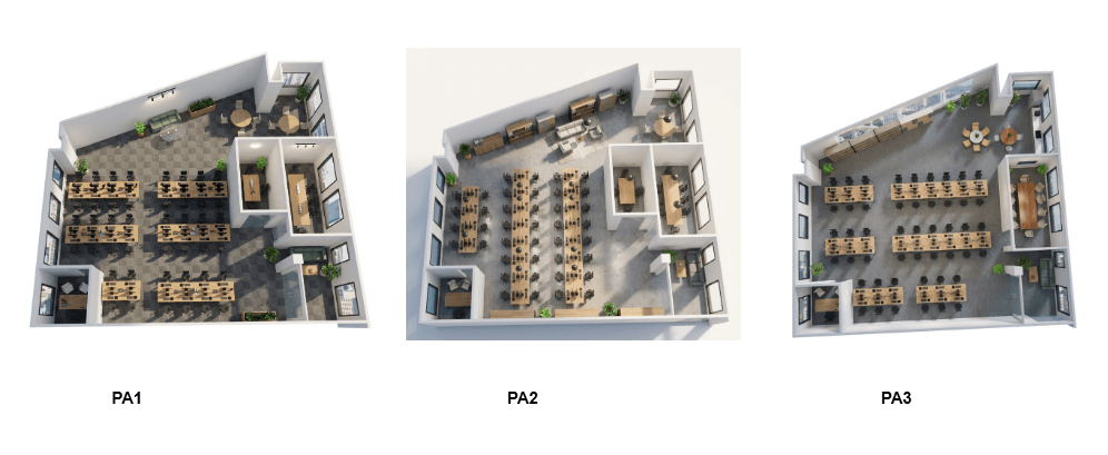
Figure 6. Layout options generated with the support of AI.
AI in this workflow plays a supporting role, not a replacement for the designer. Users still actively select the appropriate option and control the final design.
4. From layout to CAD/DXF drawing
After the layout option is selected and finalized, the next step is to convert the design result into a CAD/DXF drawing.
This is the step that connects the 3D working environment with the familiar CAD process.
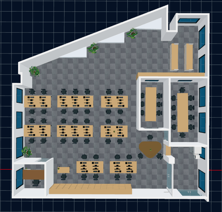
Figure 7. The final layout option on VinaCAD Web Engine.
The layout option, after being checked and adjusted, can be exported as a drawing CAD/DXF with necessary dimension information.
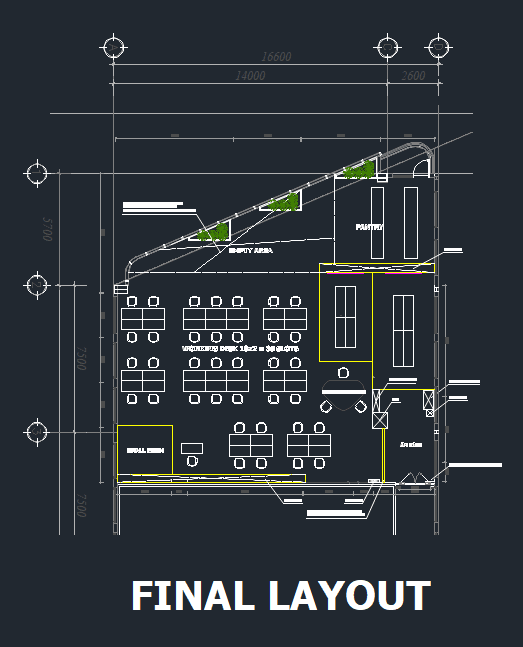
Overall drawing
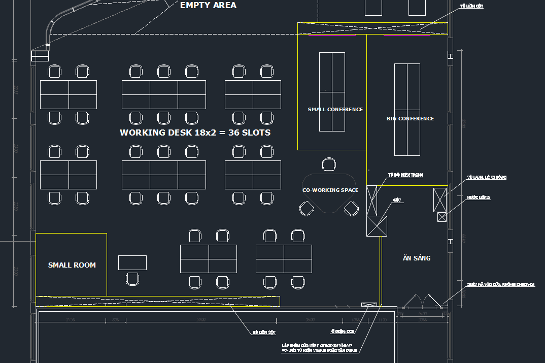
Figure 8. CAD/DXF drawing corresponding to the layout option.
The CAD/DXF drawing shows the layout information and dimensions of the option, creating a basis for further drawing development and subsequent project steps.
5. From digitizing the current state to a seamless design workflow
Office case study of approximately 200 m² shows that data generated from the scanning process can continue to be used throughout the workflow steps. The value of the workflow lies not only in creating a 3D Model, but also in the ability to continue using existing condition data in the verification, design, and drawing creation steps.
Users can proactively design according to their own ideas or use AI to explore more options before making a choice and finalizing the design as desired.
Conclusion
In the digital transformation trend of the architecture and construction industry, scanning the existing condition with 3D LiDAR is only the beginning. The real value lies in the ability to connect that existing data with the design process and automated documentation production. Scan2BIM × VinaCAD Web Engine Solution from VinaCAD is the perfect link helping businesses comprehensively digitize the interior design and construction renovation process.
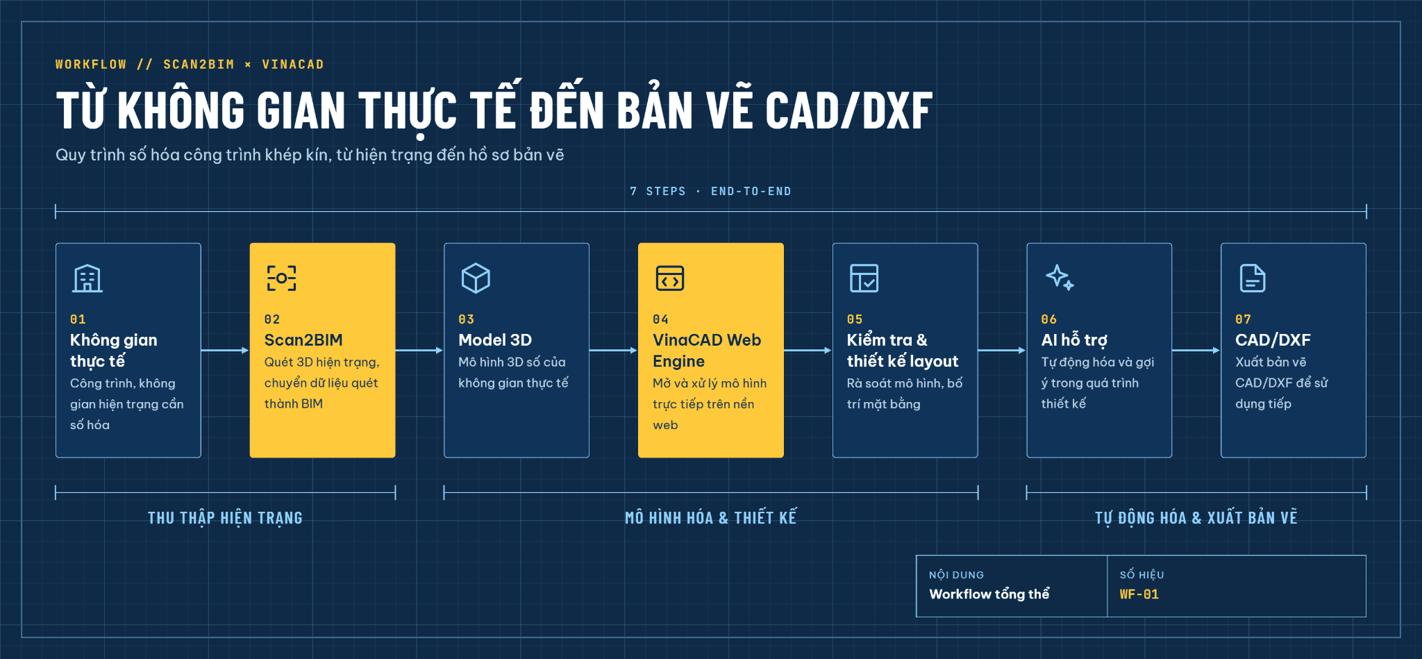
Figure 9. Closed-loop value chain diagram from Physical Space to Construction Drawings
Experience & Connect solutions
- Application Scan2BIM Mobile right on App Store (iOS)
- Zalo consultation & technical support: VinaCAD Ecosystem
- Email: vinacad@prima-sol.com / sales@tgl-sol.com